The Property Mapping Tool
You can use the Property Mapping Tool under the Tools workspace to map one or more properties between volumetric objects such as 3D grids, 3D meshes, seismic volumes.
Depending on the source and target objects, various property mapping methods are available. See the table below for an overview.
| Source | Target | Methods available |
|---|---|---|
| 3D grid | 3D grid |
XY Region, XYZ |
| 3D grid | 3D mesh | XY Region, XYZ |
| 3D grid | Seismic volume | XYZ Downscaling |
| 3D mesh | 3D grid | XY Region, XYZ |
| 3D mesh | 3D mesh | XY Region, XYZ |
| 3D mesh | Seismic volume | XYZ Downscaling |
| Seismic volume | 3D grid | XYZ Upscaling |
| Seismic volume | 3D mesh | XYZ Upscaling |
| Seismic volume | Seismic volume | XYZ |
| 3D grid |
Upscaled grid (based on the source 3D grid) |
Upscaling |
|
Upscaled grid
(based on the target 3D grid) |
3D grid | Downscaling |
XY Region (default, if available for the selected source-target combination)
The XY Region method maps based on geometric location but augmented with region information. First, a calculation is done to determine which regions on the source and target overlap or correspond to each other. This information is then used in the actual mapping between source and target.
This method can be used, for example, to map property values with sharp contrasts, such as pore pressure reduction due to production within a reservoir region of the 3D grid to the reservoir region in the 3D mesh target, while applying hydrostatic values outside the reservoir. For more details, also see the section 'Best practices in XY Region property mapping with the Property Mapping Tool'.
XYZ
The XYZ method maps based only on data locations, making it fully geometrical. Region information is only used to determine where values are mapped to but is not part of the mapping algorithm itself. This method is suitable for simple mapping operations where region information is not relevant (e.g., for properties that change gradually) when the XY Region method is not available.
Upscaling or Downscaling
The upscaling or downscaling methods map properties between a 3D grid and an upscaled version of that 3D grid created in JewelSuite (and vice versa). Upscaling averages multiple property values from the source 3D grid to a single new property value on the target upscaled grid. Downscaling converts one property value from the source upscaled grid to multiple new property values on the target 3D Grid.
XYZ Upscaling or XYZ Downscaling
Versions of XYZ with Upscaling or Downscaling are automatically selected when mapping between 3D grids or 3D meshes and seismic volumes, provided the target-source combination requires scaling.
- Open the Property Mapping Tool (Workspace > Tools > Property Mapping Tool) and select the Source object and the Target object. If the target object is a 3D mesh, also select whether you want to map to Nodes (default) or Elements.
- Go to the Methods tab:
Select the Mapping method to use. If only one method is available for the source-target combination, it will be preselected. If multiple methods are available, the default is XY Region.
- XY Region settings (Also see the section 'Best practices in XY Region property mapping with the Property Mapping Tool'):
- Select a Source regions property and Target regions property. These are typically properties such as Zone or Compartment in both the source and target object.
- Select a Region match method. This will influence what is shown in the Region Selection table (when calculated later), and how the mapping is carried out.
- Best Fit (default) will only show combinations with the best geometric match (i.e., the highest overlap). When a full overlap in property class names exists between Source regions property and Target regions property, this name match will also be taken into account. When the regions are calculated in a later step, the form will indicate whether a name based match or only a geometry match was achieved. Also see the section 'Best practices in XY Region property mapping with the Property Mapping Tool'.
- Show All will show all combinations that are found. Typically this should only be used if the desired mapping cannot be achieved with the Best Fit approach. Although Show All will give more control over what information is used in mapping, it can also more easily lead to undesired results.
- Interpolate When selected, this option performs a linear least squares (LLS) interpolation of the input data. This can smooth property values, especially when there is a large contrast between source and target resolution. However, enabling this option will increase processing time and, as with any interpolation method, may cause property values to deviate more from their original input compared to mapping without interpolation.Important The interpolation setting is not region-aware and will use all input data for interpolation, regardless of the Region Selection. In particular for cases where properties have sharp contrasts in values, using the interpolation option may lead to undesired values around this sharp contrast. For example, 'high' values in one region might influence the interpolation of 'low' values in another region (and vice versa).
- Advanced settings When you click the cogwheel
 icon, a dialog box appears to set Maximum lateral search distance and Maximum vertical search distance for the region matching algorithm. This functionality is mainly intended to reduce 'holes' and edge effects when matching source and target regions. For example, if no match is found at the exact location, the algorithm will search a bit further.The default is 100 meters for both lateral and vertical directions, and it is recommended to keep these values as they typically do not need adjustment.These settings always result in some extrapolation; increasing the distances will result in more extrapolation. However, when extrapolation is needed, it is recommended to use the Extrapolate option on the Settings tab instead.
 - Region Selection When you click the Refresh
 icon, this table updates to display the matched Target regions property and Source regions property, their overlaps, and provides options for mapping. Clicking Refresh performs the matching calculation based on your current settings.The RefreshBy default, the table automatically selects all valid combinations, except those with 'No source' (For example, when the target contains an underburden but the source does not). When a good match is found, you can manually select the target regions you want to map in the table. If the matches are not satisfactory, consider adjusting the settings and recalculate the Region Selection table by clicking Refresh process may take some time depending on the size and complexity of the model.. Also see the section 'Best practices in XY Region property mapping with the Property Mapping Tool'.
Important For the best mapping results, these properties should have a good match, indicating the same regions on both objects. For instance, properties indicating where 'Zone A', 'Zone B' and 'Zone C' are on both the source and target volumes will typically result in good region-aware mapping, as the algorithm will know what belongs together. A more incompatible combination like 'Zone A', 'Zone B', 'Zone C' for the source but 25 K-layers on the target may lead to suboptimal mapping results. More details and examples can be found in the section 'Best practices in XY Region property mapping with the Property Mapping Tool'). - XYZ Settings (also applies to XYZ Upscaling and XYZ Downscaling) For the XYZ method, you can optionally select a Target regions property, which will populate the Region Selection table. From this table, you can select which target regions you want to map properties to. If no selection is made, XYZ mapping will be applied across the entire model (everywhere where a geometric overlap is found).
- Upscaling Settings Enabling the Make impenetrable model layers undefined option will set the mapped property values to undefined in impenetrable layers, as defined in the Upscaling & Layers functionality, on the upscaled grid target.
- Downscaling Settings For downscaling, no additional settings are available.
- XY Region settings (Also see the section 'Best practices in XY Region property mapping with the Property Mapping Tool'):
- Go to the Settings tab:
- Extrapolate When selected, this option will extrapolate values in places where no property values are present after mapping (and, if applicable to the method, only within the selected target regions). Hence, extrapolation is applied as a post-processing step after mapping.
- Replace with provides an option to:
- Overwrite All Values Always overwrite all target values. This is the default and recommended option, as it ensures a repeatable mapping action recorded in the audit trail.
- Overwrite Valid Values Only Overwrite the target property only where the new mapping result has valid values. Where the new mapping result is undefined, the existing target values remain unchanged.Valid Values can be useful in cases where the desired mapping results can only be obtained by mapping in multiple stages. For example, combining different methods or settings for different regions.
- Prefix (Optional) Specify text to be added at the beginning of the mapped property name.
- Suffix (Optional) Specify text to be added at the end of the mapped property name.
The algorithm performs a simple extrapolation based on the nearest location with valid mapped data for the property. This approach is suitable in certain cases, such as small extensions to regions with no source data or larger extensions of data into regions where precise property values are less relevant (e.g., in a sideburden).
It is recommended to avoid extrapolation within the main region of interest as much as possible.You can also use a backslash (\) to create (or reuse) a property folder on the target. For example, entering 'MyFolder\MyPropertyPrefix_' will generate a folder named 'MyFolder' (if it does not already exist) and a property named 'MyPropertyPrefix_<original name>' inside 'MyFolder'.
- Go to the Properties tab:
On the Properties tab, you can select one or more properties to map from source to target. Any folder structure on the source will be preserved and carried over to the target.
If a Scaling Method is required (for upscaling or downscaling) it can be set per property in table. You can also specify a Weight Property if the selected scaling method requires it.
- When all desired settings are configured, click Apply or OK to execute the property mapping. Depending on the model size, complexity, and selected options, this process may take a some time.
For some methods, information on how the source maps to the target, known as a ‘property conversion map’, is stored internally. This cached information is reused to remap the same property more quickly or to map additional properties (when using the same mapping settings). If different settings are selected, such as a different region selection, or if the cache is invalidated in another way, it will perform a full recalculation.Mapping operations performed with the Property Mapping Tool are not remembered on the form but are recorded in the Audit Trail and can be opened from there. This way, property mapping operations can be easily audited, repeated or modified. You can also view the audit trail in the history of the property, by selecting 'View History' from the property context menu.
![]() Best practices in XY Region property mapping with the Property Mapping Tool
Best practices in XY Region property mapping with the Property Mapping Tool
One of the most common property mapping operations between volumetric objects in JewelSuite is between 3D grids and other 3D grids or 3D meshes. An example would be to map flow simulation results such as pore pressure as input to a (one-way coupled) geomechanics simulation. In such cases, the geometric match between the source and the target object can range between:
- Having a perfect geometric match with inherently matching zones. For example, if both models were created from the same input data in JewelSuite.
- Differing significantly, with completely mismatching zones and zone names. For example, if the flow simulation results are manually imported into JewelSuite and cover only the reservoir section, while the 3D mesh generated in JewelSuite is much larger and includes overburden, sideburden, and underburden.
This section provides additional background on the XY Region method and best practices for using it to achieve the desired mapping results. The focus is on selecting and creating source and target regions. The examples provided use zone information, however, the same concept can be applied to other region properties, such as compartments.
Defining Exact Region Correspondence The XY Region method delivers the best results when you explicitly define how regions correspond between the source and target objects. Each source region should map to exactly one target region, by providing source and target properties that match, share identical property class names, and have good geometric overlap. When this condition is met, the process uses data only from the regions with matching names, along with the geometric information it always uses.
Name Matching Rules and Best Fit Behavior Property mapping performs name matching only when Best Fit is selected as the Region match method and all property class names match. If there is only a partial match, the mapping falls back to geometric matching. For example, if both source and target have a region named 'Zone A' but the source has a 'Zone B' while the target has 'Zone 2', the process reverts to geometric matching. The only exception to this rule occurs when 'No source' is identified; in that case, the process may still achieve a name match for the remaining source-target combinations.
Creating Matching Region Properties for Complex Geometries Depending on the source and target geometry, different actions may be required to provide the best possible region properties to the algorithm. When both source and target were created in JewelSuite based on the same data, the default 'Zone' property may already provide a good name match and can be used directly. In other cases, such as when the target includes additional zones or the source was imported from elsewhere with different zone names, it may be necessary to modify or create a matching region property on the source and/or target, or on both.
Schematic examples
Below are schematic examples of mapping between a 3D grid and a 3D mesh. Each example shows the source on the left and the target on the right, illustrating how regions are grouped based on the selected property. The reservoir section (‘Res’) has distinct property values compared to surrounding zones and should be preserved during mapping. In real models, both the 3D grid and 3D mesh typically include additional subdivisions such as extra layers, smaller cells, and elements, which are not shown here for simplicity.
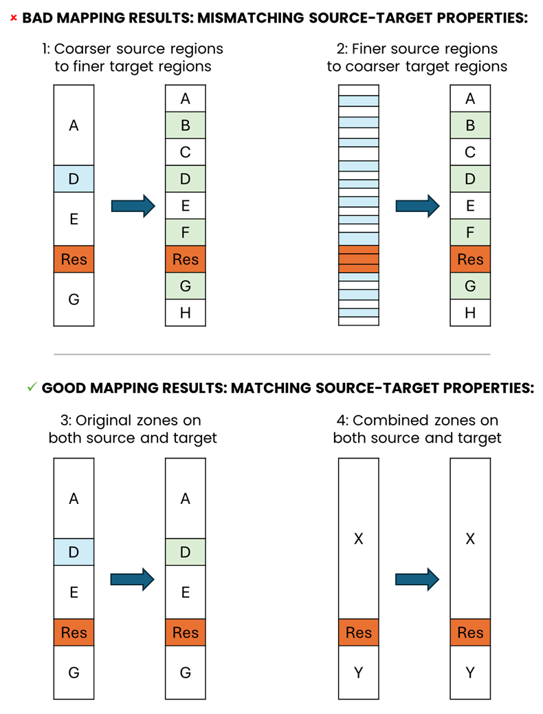
Examples of bad (1 and 2) and good (3 and 4) practices for selecting source and target region properties for the XY Region mapping method. click to enlarge
Example 1: Coarser source regions to finer target regions The default 'Zone' property is used on both the source and target, but the target has additional subdivisions compared to the source. Using these properties as Source and Target regions properties typically results in poor mapping because the source and target distributions do not match. For example, 'Zone B' is missing on the source, and 'Zone A' is much smaller on the target than on the source, which can lead to undesired sharp contrasts in property values or fail to preserve contrasts where needed.
Example 2: Finer source regions to coarser target regions The source’s fine K-layers are used as the Source regions property and the target’s Zones as the Target regions property. Although the algorithm may find a geometric match, the mapping result is often poor because the source and target represent very different resolutions. For example, the fine K-layers of the source cannot be properly linked to the much coarser target zones. Filtering based on overlap percentages may cause only part of the source data K-layers to be used, leading to undesired sharp contrasts or fail to preserve contrasts where needed.
Example 3: Original zones on both source and target There is a one-to-one match between the selected Source and Target region properties, allowing the algorithm to map zones directly (e.g., 'Zone A' to 'Zone A', 'Zone D' to 'Zone D'). This typically produces good mapping results. However, because these zones are treated independently, sharp transitions in property values may occur between adjacent zones such as 'Zone A' and 'Zone D'. If smoother transitions outside the reservoir are desired, a coarser grouping as shown in Example 4 is preferable.
Example 4: Combined zones on both source and target A coarser grouping is applied to achieve smoother transitions outside the reservoir. Zones above and below the reservoir are combined into single new properties with single larger zones (‘Zone X’ and ‘Zone Y’) in both source and target, while maintaining a one-to-one match for the reservoir itself. This approach preserves sharp contrasts at reservoir boundaries and reduces unwanted property value jumps elsewhere, resulting in a smoother mapping compared to the finer grouping shown in Example 3.
Examples from JewelSuite
The examples below show how selecting different region properties affects mapping between a 3D grid and a 3D mesh in JewelSuite. They highlight the difference between a poor mapping result when using K-layers (similar to schematic Example 2 above) and a good mapping result when using name-matching zones (similar to schematic Example 3 above).
The zonation in the 3D grid and 3D mesh is shown below:
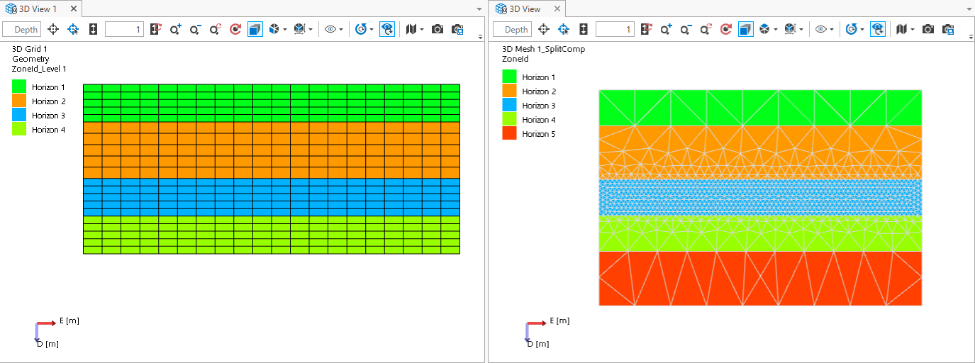
The zonation in the 3D grid and 3D mesh. click to enlarge
Poor Mapping Result When Using K-Layers In this example, K-layers are selected as the Source regions property, and ZoneID as the Target regions property. When mapping a property with a smooth gradation outside the reservoir and a sharp transition at the reservoir, the sharp transition is preserved. However, outside the reservoir, the algorithm cannot properly align fine K-layers with the much coarser mesh zones. As a result, some K-layers are skipped, and the mapping outside the reservoir is not smooth and can produce values that are significantly higher or lower than expected at those depths:
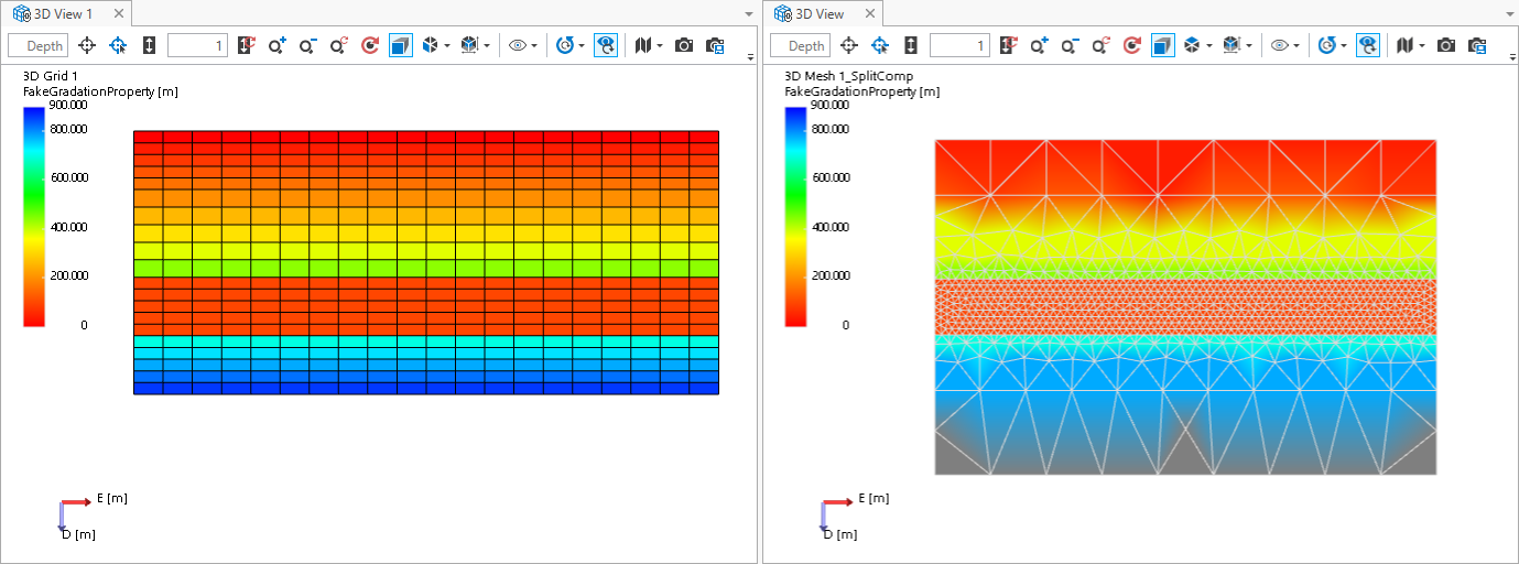
Mapping keeps the sharp reservoir transition. Outside the reservoir, misalignment between K-layers and ZoneID leads to skipped layers and uneven gradation. click to enlarge
Good Mapping Result When Using Name-Matching Zones In this example, zones from the 3D grid are used as the Source region property, and these map one-to-one to the zones on the 3D mesh. This produces a better and smoother mapping result while still honoring the sharp transition at the reservoir:
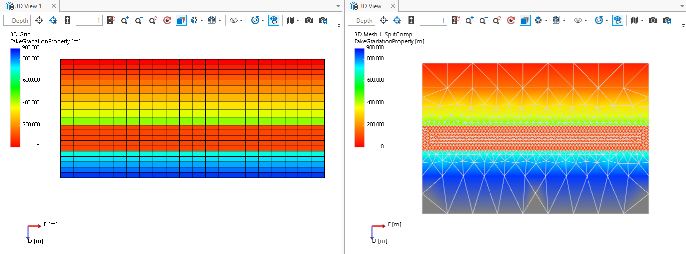
ZoneIDs on both source and target were already suitable for a one-to-one match, so no additional processing was needed to obtain the correct region properties. click to enlarge
In summary, one of the key -and often counterintuitive- takeaways from the above examples is that selecting more regions does not necessarily lead to better results in XY Region. In fact, it can often have the opposite effect (as seen in the K-layer example). The best practice is to carefully choose the coarsest region information needed for mapping and use only those regions (as shown in the final example). This also means avoiding situations where many source regions contribute to a single target region -or vice versa- in the Region Selection table. The better the Source and Target region properties are defined up front, the fewer iterations are required to achieve the desired mapping result. Additionally, matching a small number of well-aligned zones typically performs better than attempting to match many poorly aligned zones.